For constant Load Torque TL Ia1 TL Ka Ø1. Produce a steady voltage.

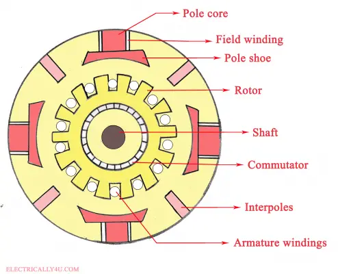
Construction Of Dc Motor Parts Images Electrical4u
Because of the parallel connection full voltage is applied to the field winding.
. Consider the animation of a basic machine shown below. The field winding basically form an electromagnet that produces field flux within which the rotor armature of the DC motor. If the process is partially reversed by electrically exciting the stator mounted field and providing torque from an external prime-mover the machine becomes a generator.
A DC machine is an electromechanical energy alteration device. Flux produced by field coils emerges from N pole and cross the air gap to enter the armature tooth. In case of turbo alternators the rotor windings or the field windings are distributed in the rotor slots.
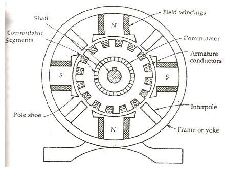
Magnetic circuit of dc machine comprises of yoke poles airgap armature teeth and armature core. Magnetic Field System of DC Generator. The static part is stator and moving part is rotor.
In this type of DC machine the field winding is connected in parallel with the armature winding. We will consider three basic types of DC machine where the operation is dependent on a field winding. As Ø1 Ø2 therefore Ia1.
Magnetic Frame and Yoke. A state feedback gain matrix is designed for the dc motor with the help of pole-placement technique. Normally 70 of the rotor is slotted and remaining portion is unslotted in order to form the pole.
Construction of DC Machines. These various parts of DC Generator are described below in detail. In a DC generator when the coil placed in the magnetic field is rotated by means of a prime mover or any handle.
The modular design of the training system allows for applications which go above and beyond the. In stator of dc machine there is a frame that provides protection and support to internal structure from external environment in this frame there are. The performance of dc motor under various conditions is simulated using MATLABSIMULINK environment and simulation result demonstrates the feasibility of the proposed system.
Combinations of the two are sometimes used. System the inductive effect caused by the induced-electric field causes skin and proximity effects. Describe the procedure for design of interpoles of DC machine.
Pole Cores and Pole Shoes. It produces the main magnetic flux. Design of the field System.
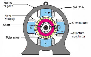
This induced Emf develops current in the armature winding. In the structure of DC machine either dc motor or generator there are 2 main parts first one is the static or the second one is moving. There are two ways to adjust the speed of a wound-field dc motor.
The coils cut the magnetic lines of forces to induce an EMF. The rotor construction of the turbo alternator is as shown in fig. The DC machines are classified into two types such as DC generator as well as DC motor.
Find the main dimensions of the machine if it has to. Dhruvang R Gayakwad Assistant Professor 26 A. There are two stages remaining before a dc machine can be produced.
The path of magnetic flux is called magnetic circuit. Design of Commutator Brushes. Now ωm1 Vt Ia1Ra Ka Ø1.
Electrical Machines and Drives Third Edition 1996. DC motor Fall15 Revised. It provides mechanical support for the poles and acts as a protecting cover for the whole.
Basic principles of the DC shunt motor _____ 5. Describe the procedure for design of field system of DC machine. The field magnets consist of pole cores and pole shoes.
The magnetic field system consists of Mainframe or Yoke Pole core and Pole shoes and Field or Exciting coils. The electromagnetism review also showed how it is possible to create a constant magnetic field using direct current. Besides if the DC motor is used to drive an external torque T L t of payload then its mechanical behavior is described as t B t T t T t dt d t J M L 2-10 where J M is the rotor moment of inertia and B M is the frictional coefficient.
Based on 2-8 2-9 and 2-10 the dynamic equation of the DC motor can be expressed as. Suppose Ia1 Armature current of DC Shunt Motor when Field Flux Ø1 and speed ωm1. Ia2 Armature current of DC Shunt Motor when Field Flux Ø2 and speed ωm2.
Rectify the voltage to produce a direct non-alternating current. Of dc motor using state space approach. November 4 2016 9 of 21 The DC motor creates torque from electrical excitation of two magnetic circuits the field and the armature.
System the current distribution through the cross-section of a current-carrying conductor is uniform as it consists of only the resistance. The field winding of DC motor are made with field coils copper wire wound over the slots of the pole shoes in such a manner that when field current flows through it then adjacent poles have opposite polarity are produced. In a PM DC machine the armature circuit model is the complete circuit model and kphi is constant.
These effects play a complex role in determining the current distribution through the. BE - ELECTRICAL ENGINEERINGSubject. Construction of DC Machine Generator Motor 1.
The working principle of a DC machine is when electric current flows through a coil within a magnetic field and then the magnetic force generates a torque that rotates the dc motor. Machine a torque angle of 90 is the normal condition with field and armature mmfs maintained in quadrature by the angular-position switching action of brushes and commutator. Basic principles of 3-phase machines In the field of drive technology DC drives currently play a major role in mobile drive solutions.
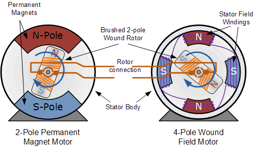
Many modern DC machines are constructed with a permanent magnet PM field which results in a constant flux. The Magnetic Field System is the stationary or fixed part of the machine. Overview of direct current machines _____ 3 Exercise 1.
Design of Field Poles Field Coils. 2160912 - Design of DC Machines and Transformer Sem-6Created By. Reel drives require this kind of control.
A 5 kW 400 V 4 pole 1500 rpm DC shunt generator has the average flux density in the airgap as 12 Wbm 2 and the specific electric loading is 21000 Am. Ia2 TL Ka Ø2. Therefore shunt winding is designed with a large number of turns with high resistance.
What Are Wound Field Motors And Where Are They Applied
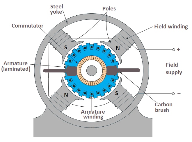
Construction Of Dc Motor Your Electrical Guide
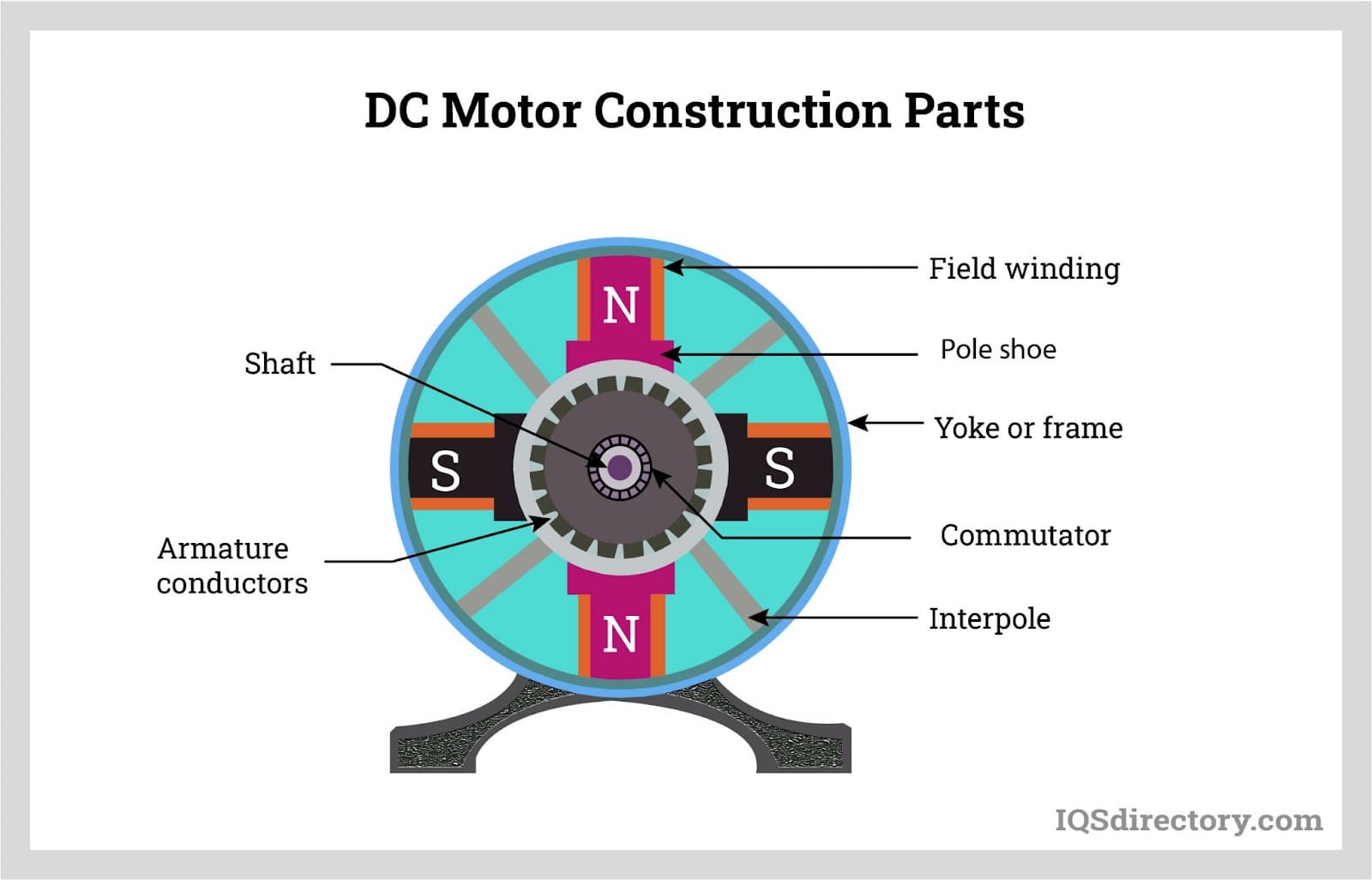
Dc Motor What Is It How Does It Work Types Uses
Construction Of Dc Generator

Construction Of Dc Machine Generator Motor
Construction Of A Dc Generator Explanation Of Its Various Parts Circuit Globe
Dc Machine Construction Working Types Emf Equation Applications

Construction Of Dc Machines The Engineering Knowledge
0 comments
Post a Comment